Upgrading a Data Center Network from 10G to 25G and 100G

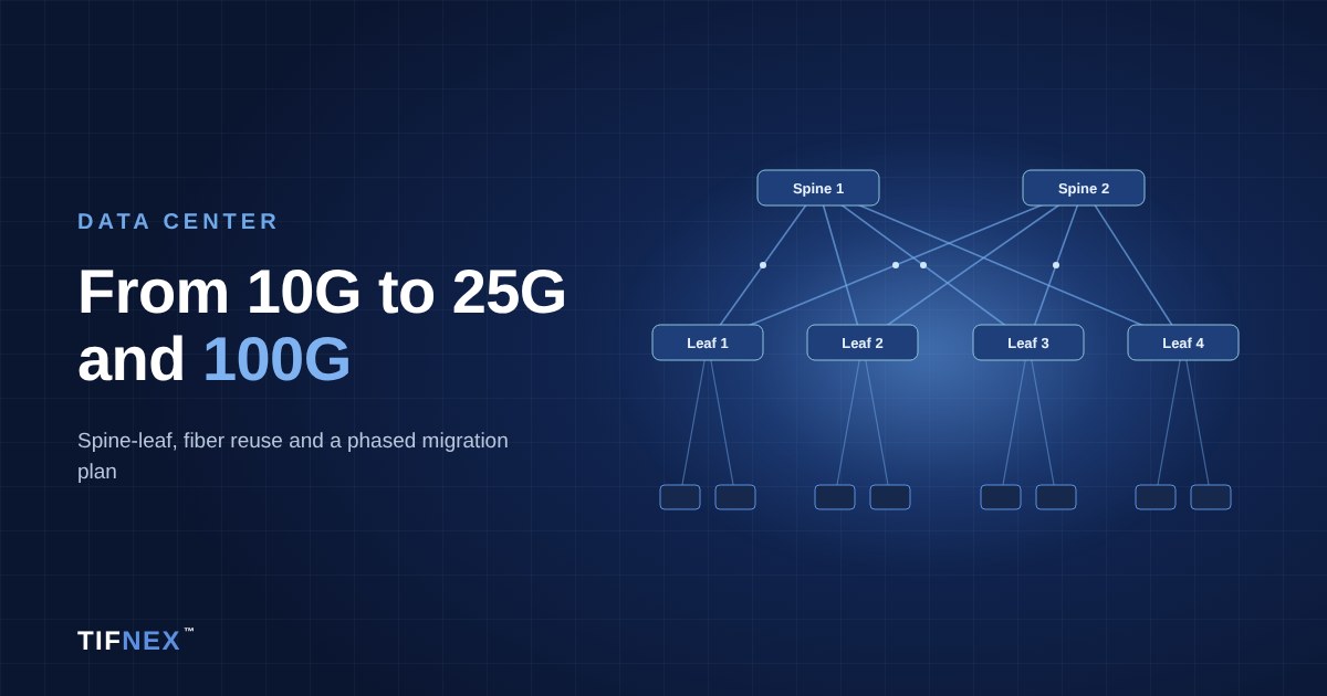
A typical data center network upgrade from 10G moves servers to 25G SFP28 and switch uplinks to 100G QSFP28, usually in a spine-leaf design. The jump is cost-effective because 25G and 100G share the same 25G lane rate, so one 100G port can break out to four 25G servers and the optics, DACs and switch silicon all line up.
The hard parts are rarely the switches. They are the existing fiber plant, the change in reach at higher speeds, and moving production traffic without an outage. This guide covers the design choices, what you can reuse, a phased migration plan and the point at which it makes sense to skip straight to 400G.
Why 25G Servers and 100G Uplinks
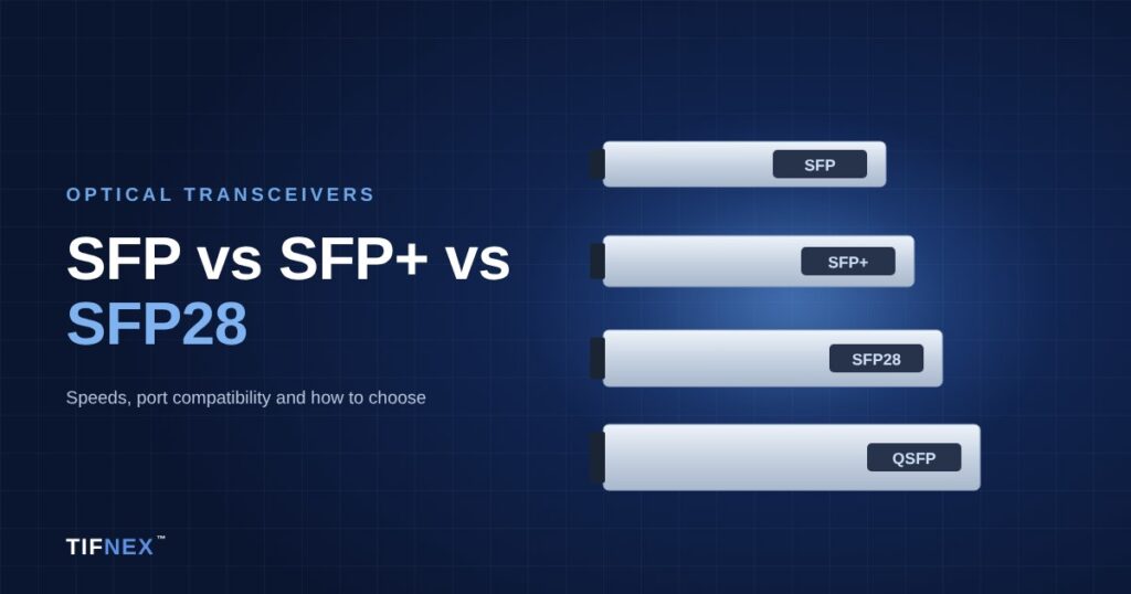
10G SFP+ uses a single 10G lane. 25G SFP28 uses a single 25G lane in the same physical form factor, and 100G QSFP28 bundles four 25G lanes. That shared lane rate is why 25G/100G became the standard step up from 10G/40G.
- 2.5 times the bandwidth per server port with the same cable count and similar power per port.
- Backward compatibility: most SFP28 switch ports accept 10G SFP+ optics with the port speed set to 10G, so servers can move over one at a time. Check your platform’s support list.
- Clean breakout: one 100G QSFP28 port splits into 4 x 25G with a breakout DAC or an SR4 harness.
- Uplinks scale: 100G uplinks replace bundles of 10G or 40G links and simplify ECMP and LAG designs.
Spine-Leaf Design and Oversubscription
Many 10G networks still run a three-tier core, aggregation and access design with spanning tree. An upgrade is a good time to move to spine-leaf. Each leaf (top-of-rack) switch connects to every spine, and traffic between any two servers crosses at most one spine. Routing with ECMP replaces spanning tree, so all uplinks carry traffic at the same time.
Working out oversubscription
Oversubscription is the ratio of server-facing bandwidth to uplink bandwidth on a leaf. A common leaf has 48 x 25G downlinks and 8 x 100G uplinks:
- 48 x 25G = 1,200G towards servers.
- 8 x 100G = 800G towards the spines.
- Ratio 1,200 : 800 = 1.5:1.
Using only 6 uplinks gives 2:1, and 4 uplinks gives 3:1. General virtualisation and enterprise workloads usually run fine at 2:1 to 3:1. Storage-heavy, east-west-heavy or AI workloads need closer to 1:1. Decide the target ratio first, because it sets the number of spine ports, optics and fiber pairs you need.
Spines are commonly 32 x 100G switches, so the number of spine ports limits how many leaves you can attach. Plan for growth: if the fabric is likely to double, consider 400G spines from the start, covered below. See data center switches for leaf and spine models.
Reusing Existing Fiber
This is where many upgrades get stuck. Fiber that ran 10G perfectly well can be too long, or the wrong grade, for 25G and 100G multimode.
| Standard | Fibers / connector | OM3 | OM4 | Single-mode |
|---|---|---|---|---|
| 10GBASE-SR | 2 / LC duplex | 300m | 400m | n/a |
| 25GBASE-SR | 2 / LC duplex | 70m | 100m | n/a |
| 100GBASE-SR4 | 8 / MPO-12 | 70m | 100m | n/a |
| 100G-SWDM4 / 100G BiDi | 2 / LC duplex | 70 to 75m | 100m | n/a |
| 25GBASE-LR | 2 / LC duplex | n/a | n/a | 10km |
| 100G-DR / 100G-FR | 2 / LC duplex | n/a | n/a | 500m / 2km |
| 100G-CWDM4 / 100G-LR4 | 2 / LC duplex | n/a | n/a | 2km / 10km |
Practical points:
- OM1 and OM2 are not specified for 25GBASE-SR or 100GBASE-SR4. Plan to replace them.
- OM3 runs over 70m that carried 10G will not carry 25G or 100G SR. Measure, do not estimate from drawings.
- Duplex LC multimode trunks cannot carry 100GBASE-SR4, which needs 8 fibers on MPO. Use 100G-SWDM4 or 100G BiDi to reuse duplex plant, or move to single-mode.
- Existing single-mode is the easiest to reuse. 100G-CWDM4, 100G-DR and 100G-FR all run on a duplex pair.
Loss budgets are much tighter at these speeds. 100GBASE-SR4 allows under 2 dB of channel loss, so a link with two or three mated connector pairs can fail even within reach. For new runs, many teams install OS2 single-mode with MTP/MPO trunks and cassettes, which supports 100G now and 400G-DR4 later.
Optics vs DAC: Choosing the Physical Layer
Each link type has a natural fit:
- Server to leaf, same rack: 25G SFP28 DAC. Lowest cost and power. Passive 25G DAC is commonly used up to 3 metres, with longer lengths needing RS-FEC.
- Server to leaf, adjacent rack or end-of-row: 25G AOC, or 25GBASE-SR optics on OM4 for structured cabling.
- Leaf to spine, same row: 100G AOC or 100GBASE-SR4 on OM4.
- Leaf to spine, across halls or over 100m: 100G-CWDM4, 100G-DR or 100G-FR on single-mode.
Set FEC deliberately. 25GBASE-SR and 100GBASE-SR4 need RS-FEC, and a mismatch between switch and NIC is one of the most common reasons a new 25G link stays down. Browse 25G SFP28 and 100G QSFP28 transceivers.
Using breakout during migration
Breakout is useful in two places. On the leaf, a 100G port split into 4 x 25G adds server ports when the fixed SFP28 ports run out. In the core, a 100G spine port can break out to 4 x 25G uplinks to an older leaf during the transition, or a 40G QSFP+ port can split into 4 x 10G to keep legacy access switches connected. Each breakout needs the switch port set to the matching mode. Our breakout cables guide explains the mappings and pitfalls.
A Phased Migration Plan
Running both networks side by side for a period is normal. A typical sequence:
- Audit. List every server NIC, switch, optic and fiber run with its type, length and connector. Note which servers already have 25G-capable NICs.
- Test the fiber. Inspect, clean and loss-test each trunk you plan to reuse. Mark each as fit for 25G/100G, single-mode only, or replace.
- Design the target fabric. Spine and leaf count, oversubscription ratio, IP addressing, routing protocol, and the uplink from the new fabric to the old core.
- Build the spines and a pilot leaf pair. Connect them to the existing core with routed links, often at 40G or 100G, and run test workloads.
- Migrate rack by rack. Install new leaf switches per rack or pair of racks, move servers over in maintenance windows, and keep a rollback path.
- Move shared services last. Storage, firewalls, load balancers and WAN edge move once the fabric is proven.
- Retire the old layer. Remove legacy switches, recover optics and update documentation and monitoring.
For teams without spare engineering time, TIFNEX can supply hardware and support the work through our network installation service.
Testing and Cleaning Before Go-Live
Dirty connectors cause more failed 25G and 100G links than faulty optics. At these lane rates the margin is small, and one contaminated end face can push a link over the edge.
- Inspect every end face with a fiber scope before mating, including new patch cords straight out of the bag.
- Clean, then inspect again. Use click cleaners for LC and dedicated MPO cleaners for MPO ends. See fiber cleaners.
- Loss-test with the right method. Tier 1 testing with a light source and power meter, using MPO-capable test kit for parallel links.
- Check optic diagnostics. After go-live, record transmit and receive power from DOM/DDM on each link as a baseline, and watch FEC corrected and uncorrected error counters.
When to Jump Straight to 400G
If you are building a new fabric in 2026, compare a 100G spine with a 400G spine before you buy. 400G makes sense when:
- The spine would need more than 32 x 100G ports within the next few years.
- Servers are moving to 100G NICs, as is common for GPU, storage and high-density virtualisation hosts.
- You are running AI training or inference clusters with heavy east-west traffic.
A useful middle path is 400G spines with 100G leaf uplinks: a 400G-DR4 port on the spine breaks out to four 100G-DR leaf uplinks over single-mode fiber. Many QSFP-DD ports also accept QSFP28 modules, which helps during transition. See 400G transceivers, and our AI data center networking guide if GPU clusters are part of the plan.
Upgrade Checklist
- Target speeds per tier: 25G servers, 100G uplinks, or 100G servers with 400G spines.
- Oversubscription ratio agreed and spine port count sized for growth.
- Fiber audit complete, with each run tested and rated.
- Physical layer chosen per link: DAC, AOC, multimode or single-mode optics.
- FEC, breakout modes and optic coding confirmed for every switch and NIC model.
- Cleaning and inspection kit on site, and a baseline of optical power recorded.
- Migration sequence and rollback plan written down.
Frequently Asked Questions
Why upgrade from 10G to 25G instead of 40G?
25G uses a single lane per port, the same as 10G, so it gives 2.5 times the bandwidth with the same cabling and similar power per port. 40G needs four lanes and more fibers per link, and 25G pairs naturally with 100G uplinks through 4 x 25G breakout.
Can I use my existing OM3 fiber for 25G and 100G?
Yes, if the runs are short enough. 25GBASE-SR and 100GBASE-SR4 reach 70 metres on OM3 and 100 metres on OM4, compared with 300 metres for 10GBASE-SR on OM3. Test every run for length and loss before reusing it.
Will 10G SFP+ modules work in 25G SFP28 ports?
On most switches, yes, once the port speed is set to 10G. Support depends on the switch platform and its optics list, so check before relying on it for migration.
What oversubscription ratio should a leaf switch have?
General enterprise and virtualisation workloads usually run well at 2:1 to 3:1. Storage-heavy, east-west-heavy and AI workloads need closer to 1:1. For example, 48 x 25G downlinks with 8 x 100G uplinks gives 1.5:1.
Should I use DAC or optics between servers and leaf switches?
Use DAC for servers in the same rack as the leaf switch, since it has the lowest cost and power. Use AOC or optics with structured fiber for links to other racks or end-of-row switches.
Talk to TIFNEX
Planning a data center network upgrade? Send us your current switch and NIC models, target speeds, fiber types and distances, and the quantities per rack, and we will propose matched, compatibility-coded optics, DACs, AOCs and cabling with a quote within 24 hours. TIFNEX delivers across the UAE, Egypt and the wider GCC. Contact our engineers or message +971 54 300 8970 on WhatsApp.